Jun. 23, 2020
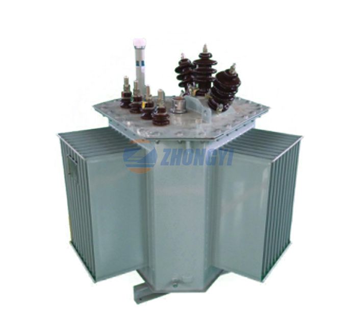
Three-phase transformers are used to transmit large amounts of electrical energy. The three-phase transformer is a voltage boosting and step-down device for each stage of the power system network. The three-phase transformer has two structures.
1. Three-phase transformer should be connected to three-phase operation.
2. A three-phase transformer in which all three-phase magnetic cores and windings are combined into one structure.
When the primary and secondary windings of a three-phase single-phase transformer are connected, they can be used as three-phase transformers. Compared with three single-phase units, the three-phase transformer power supply has many advantages, such as the space it requires is very small, and the volume is smaller and the cost is lower. Three-phase transformers are mainly divided into two categories, namely core transformers and shell transformers.

Iron core three-phase transformer
Consider a three-phase single-phase iron core transformer, 120° apart. If a balanced three-phase sinusoidal voltage is applied to the winding, the magnetic fluxes φa, φb, and φc will also be sinusoidal and balanced. If the three legs carrying these fluxes are combined together, the total flux in the combined legs becomes zero. Therefore, this leg can be removed because it carries no flux. This structure is not easy to take the core.
The core of a three-phase transformer is usually composed of three branches on the same plane. This can be built using stack lamination. Each branch of the core has low-voltage and high-voltage windings. The low-voltage winding is more insulated from the iron core than the high-voltage winding.
The low winding is placed next to the core, with proper insulation between the core and the low voltage winding. The high-voltage winding is placed on the low-voltage winding with proper insulation between the low-voltage windings. The magnetic circuit of the legs a and c is larger than that of the leg b, and the structure is asymmetric, resulting in unbalanced magnetic current.
Shell three-phase transformer
The shell-type three-phase transformer can be formed by stacking three single-phase shell-type transformers. The winding direction of the central unit b is opposite to the winding directions of the units a and c. If the system is balanced with the phase sequence a-b-c, the magnetic flux will also be balanced.
The size of this combined flux is equal to the size of each component. The cross-sectional area of the combined yoke is the same as the cross-sectional area of the outer leg and the cross-sectional areas of the top and bottom of the yoke. The unbalanced magnetic circuit has little effect on the performance of the three-shell transformer. The windings of the shell-type three-phase transformer can be connected in a triangle or star as required.
The above information is provided by transformer manufacturer.
Previous: What Fuel Does the Transformer Use?
Next: What Is a Transformer?
Contact Us
Contact us. Together with us, inspire boundless creativity
NAVIGATION
Tel: +86 312 5880165
Mob: +86 135 1322 2010
Fax: +86 312 5880165
E-mail: gracejia@zydqjt.com
Skype: +86 135 1322 2010
WhatsApp: +86 135 1322 2010
Wechat: +86 135 1322 2010
FOLLOW US
Add: Room A1109, No.483 Yulan Street, Baoding City, Hebei Province, China
